- Multiple pressure transmitters with fast response time strategically installed throughout the pipeline.
- Multiple Field Signal Processor (FSP) units associated with the high-performance pressure transmitters and equipped with GPS antennas.
- LDS Master Central Controller (CC) unit that communicates with FSP units, collects data, and makes leak decisions.
- A Central Monitoring Station (CMS) for supervisory and configuration operations.
Pressure Transmitters
The WAVEGuard® system uses IEC certified explosion-proof / intrinsically-safe pressure transmitters. These pressure transmitters are responsible for pressure signal acquisition and transmission. Many enclosure types are available to accommodate various client requirements. Pressure transmitters are connected to the pipeline through a riser and a 2″ tap (typically). Pressure transmitters can be installed on a pressurized pipeline using the Hot-Tapping process to eliminate costly shut downs.
The pressure transmitters require 10-30 volt supply (24 VDC typically) provided by the FSP unit and they output a 4-20 mA current signal. The connection between the pressure transmitters and the FSP unit requires a standard two wire instrumentation cable.
These high-quality pressure transmitters have sampling rate of 1000 samples per second, and are strategically installed at various locations along the pipeline. The distances between intermediate pressure transmitters vary and depend on the overall expected system performance, pressure signal attenuation through the fluid, and availability of power and communication link. A typical distance between two intermediate pressure transmitters is in the order of tens of kilometers. The distance between the two end pressure transmitters should be around 125-150 meters.
The use of a pair of pressure transmitters at the two ends of the pipeline allows for the identification and rejection of external operational noises generated outside the monitored segment that otherwise could cause false alarms.
Global Positioning System (GPS)
The WAVEGuard® LDS system requires its own internal GPS system, with nano second accuracy, that is fundamental to its operation. The GPS acquires the time from the satellite and makes it available for the FSP units and the LDS Master CC unit to time-stamp all events. This accurate (nano second) determination of time at the LDS Master CC unit and the various FSP units is essential for the analysis of pressure waves traveling at the speed of sound, and for determining the location of a potential leak. The GPS antenna is shown in the figure below.
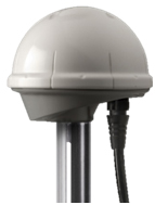
GPS Antenna
- The GPS device contains a micro-processor for its operation.
- The GPS device locates the satellites upon power-up and configuration, and starts receiving the timing information.
- This device can give output in industry standard NMEA protocol or customized TSIP (Trimble standard interface protocol) protocol.
- The GPS device has timing accuracy and resolution in nano seconds which makes the time stamping of pressure signals & events very precise, which is required for the leak detection function and for calculating leak location with the highest accuracy.
- This device has wide operating temperature range, waterproof and corrosion resistant, which make it suitable to use in extreme conditions such as in unsheltered areas.
The GPS antenna is used by the LDS Master CC unit and by every FSP unit so that all events detected by the FSP unit are being time stamped. This is necessary because the time stamping from all FSP units is compared by the CC unit to declare a genuine leak and provide leak location.
Physical Interface
The RS-422 interface is used, and is ideal for long cable runs required by buildings or towers. Standard cables are available in lengths up to 1800 feet may be ordered.
Field Signal Processor (FSP) Unit
The FSP unit/panel is an integrated field-grade outdoor system which includes modules for data acquisition, signal conditioning, noise filtering, data processing and communication. PipeTech designs and manufactures the outdoor and environmentally-hardened FSP units to operate under harsh environment and extreme temperatures. A typical FSP unit enclosure is shown below.
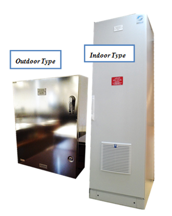
FSP Unit Enclosure
At the heart of the FSP unit is the FSP processor, and the WAVEGuard® system uses the world renowned CompactRIO® from the National Instruments Corporation (a US-based company) as its hardware processor platform. The CompactRIO®, is a Programmable Automation Controller (PAC) that offers a rigid hardware platform with powerful processing unit that is capable of performing real-time signal acquisition and control operations. This system is a ruggedized product that operates in the harshest environments and has been used by leading oil and gas companies in the world such as Shell Global Solutions, Petrobras, Halliburton, and others.
The FSP units are housed inside cabinets/enclosure in the field, and installed in close proximity to the pressure transmitters (typically within 500-1000 meters but actual distance is determined by the site topology). Those cabinets/enclosures are normally placed in field equipment shelters. Multiple pressure transmitters can be supported by a single FSP unit; thus a single FSP unit can accommodate multiple monitoring points (and pressure transmitters) of different parallel pipelines.
Pressure transmitters are connected to the FSP unit over standard 4 to 20 mA instrumentation cables. During communication faults, the FSP units are designed to remain operational and will store all events in its internal memory. Events data will then be transmitted with precise time stamps to the Central Controller Unit as soon as the communication link is restored. This is referred to as the store-and-forward feature, and is an important advance feature of the WAVEGuard® LDS system.
The FSP units acquire data from the pressure transmitters at rate of 1000 samples per second (that is 1 msec sampling rate). After passing several levels of analog and digital filtering, the initial readings are averaged and processed. The FSP units are responsible for:
- Data acquisition
- Electrical noise filtering
- Pressure signal filtering
- Event detection
- Time stamping
- Communication
The FSP unit performs advanced digital signal processing functions to detect potential leaks, and then issues/transmits leak events with precise time stamps to the Central Controller (CC) unit for further analysis. The FSP unit/cabinet can be fitted with touchscreen panel to simplify the interface with the unit.
Maintenance personnel can perform calibrations, maintenance, as well as process variations and fault clearance without the need for a portable computer in the field. Relay outputs can also be provided to drive external devices.
The built-in Global Positioning System (GPS) is used to obtain the highest accuracy in synchronizing the internal clocks of all the processors in the system. This is vital to ensure accuracy in leak location calculations.
In the absence of any event from the pipeline, a “keep-alive” (heartbeat) signal is sent from the FSP units to the Central Controller (CC) unit to indicate proper connectivity status.
Central Controller (CC) Unit – LDS Master
The CC unit is the brain of the WAVEGuard® LDS system, and is often referred to as the LDS Master. It is responsible for collecting leak events from all the FSP units in the system, performing advanced analysis, and determining if a leak has really occurred. Thus the main function of the CC unit is to sort through the events, while considering a variety of operational and environmental conditions, and then declare & locate the leak.
The CC unit is connected with the Central Monitoring Station (CMS) computer via client provided backbone communication network using TCP/IP protocol. Other communication means can also be utilized such as copper cable, optical fiber, GPRS, radio, or satellite.
As part of the engineering services provided by PipeTech, media and protocol converters are provided on a case-by-case basis according to client’s requirements and type of communication network availability.
The CC unit communicates with the Central Monitoring Station (CMS) and sends “alive” signal to indicate its state.
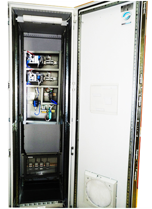
CC Unit System Cabinet
Central Monitoring Station – CMS
The CMS, which is typically referred to as the LDS Computer, provides a number of vital functions to assist the operator in the control room, including an HMI interface for entering system parameters, viewing alarm declaration, fault indication, historic database management and storage, reports generation, interfacing with external SCADA systems, and initiation of signals for valve control. Configuration parameters and operating conditions are entered into the supervisory software through user friendly engineering screens. The CMS supervisory computer can seamlessly interface with any existing SCADA system where all local and remote operations, including operational parameters, can be viewed
The Human Machine Interface (HMI) is highly customizable to client’s requirements and features pictographic screens illustrating pipeline geographical views and highlighting the monitored points along with many other critical system information elements, as shown in the figure below.
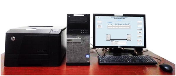
Central Monitoring Station (CMS)
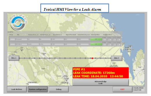
Central Monitoring Station with User-friendly HMI
Configuration parameters and operating conditions are entered into the supervisory software through user friendly engineering screens. The above screen-capture demonstrates the layout of a pipeline segment with two monitoring stations. When a leak is detected and confirmed, an alarm will sound off and the screen will change to show the exact location of the leak with date and time.
The CMS computer is responsible for various informational, communication, security and diagnostic functions. In addition, it manages and maintains an intricate database and reports as well as historical event logs with printing facility.