WAVEGuard®LDS system typical deployment in a pipeline is shown below. In this simple example two pressure transmitters are placed at each end of the pipeline and one pressure transmitter is placed in the middle to create 2 segments. The length of each segment could range from 10 to 20 km, based on the fluid type and characteristics, and the operating conditions of the pipelines. Gas pipelines typically require shorter segments for best detection performance.
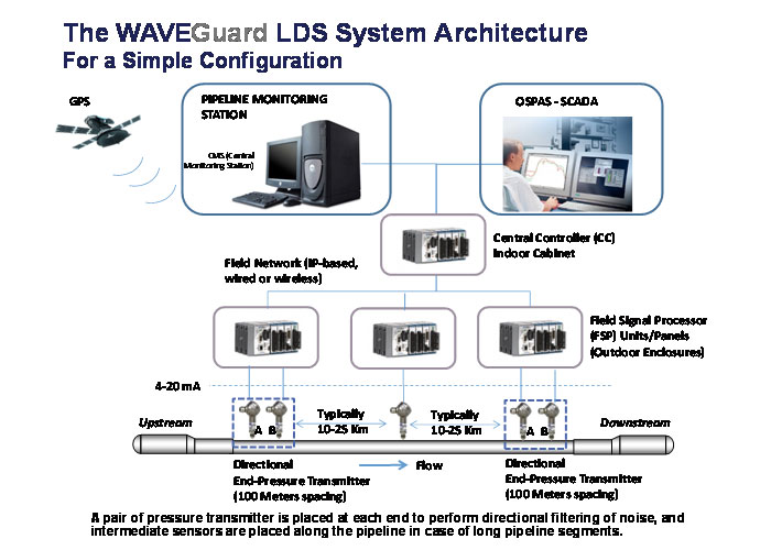
The two pressure transmitters at each end are required to help the LDS system filter out noise arriving from outside the protected pipeline segments. Any field network can be used for the communication between the FSP units and the CC unit, and any communication network can be used for the communication between the CC unit, CMS, and the SCADA system.
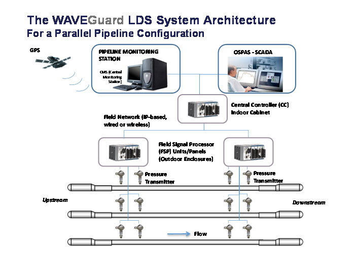
Please note that this is just a typical configuration and the WAVEGuard® systemcan accommodate a pipeline of any length and topology.