Operating Principles of Negative-pressure Wave Acoustic Leak Detection System
It is widely known that the negative-pressure wave (also known as acoustic) leak detection method is one of the latest and most powerful computational pipeline leak detection methods due to the fact that it processes real-time dynamic events in the pipeline, due to its fast response time (within a minute), and due to its ability to locate the leak position along the pipeline with good precision.
The operating principle for a negative-pressure wave acoustic leak detection system is elegant and powerful. When a leak occurs, a drop in pressure will happen at the location of the leak. This causes pressure oscillations in the fluid which propagate as pressure wave signals at the speed of sound, through the fluid and away from the leak location in opposite directions.
By placing pressure sensors and associated communication equipment along the pipeline, thenegative-pressure wave acoustic leak detection system will detect the transient pressure wave associated with the pipeline leak. In the literature the traveling wave is often referred to as a “negative pressure” wave, or the “expansion” wave.
The figure below shows the basic concept of a negative-pressure wave acoustic leak detection system.
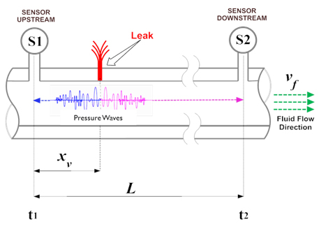
Basic Concept in a Negative-pressure Wave Acoustic Leak Detection System
As shown, when a leak occurs, the sudden drop in pressure at the leak location causes oscillation in the fluid pressure that propagatesas a negative-pressure wave in both directions, upstream and downstream, guided by the pipeline wall. High performance pressure sensors/transmitters (designated as S1 and S2) installed at opposite ends of the protected pipeline segment will detect the drop in pressure and transmit the oscillating pressure signals to their corresponding Field Signal Processor (FSP) units/panels.
The FSP unit/panel is an integrated field-grade outdoor system which includes modules for data acquisition, signal conditioning, noise filtering, data processing and communication. The FSPunit first appliesconditioning and filtering functions to separate leak signals from the background noise, and then applies advanced detection algorithms to determine if a leak “event” took place. The FSP units take into account fluid velocity (Vf), viscosity, pressure, and other pipeline specific parameters. Moreover, all leak events detected locally by the FSP units are time stamped using the GPS system.
The FSP units (two or more, based on pipeline length) then transmit the leak event(s) to the Central Controller (CC) unit, with the time stamp, which analyses events coming from the FSP units. By performing real-time computation and applying a variety of advanced algorithms, the CC declares if a leak has occurred or not, and it will then compute its location.
The location of the leak is computed based on the pressure wave propagation velocity in the fluid, by examining the difference between wave arrival times (t1 – t2) at the two opposing sensors (S1 and S2), and the length of the pipeline segment, as shown in the equation below.
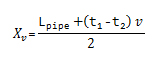
Where,
Xv = Distance from segment end to leak location
Lpipe = Length of this pipe segment
v = Negative-pressure wave traveling velocity in the fluid
t1 = Detection time at sensor S1
t2 = Detection time at sensor S2
It should be noted that not every pressure-based leak detection system is considered as a negative-pressure wave acoustic LDS system. In fact, many of the pressure sensors (and associated computing equipment) that are commonly used in traditional pressure-based leak detection systems (such as pressure point analysis, or PPA) do not qualify to be part a negative-pressure wave acoustic LDS system due to their low sensitivity, slow sampling rate, and/or response time.
At PipeTech we use the best pressure sensors in the industry such, as the WIKA E10/IS-20 pressure sensors/transmitters, which have accuracy of 0.5% of scale or better, non-repeatability of 0.1% of scale or better, and response time of 1 msec or better.
Operating Principles of Mass Balance Leak Detection System
In this mode of operation the WaveGuard® LDS System monitors the inflow of fluid in the pipeline at the upstream, the outflow of fluid at the downstream, and takes into account the line packed fluid in the segment to determine the mass of fluid injected and delivered.
Any change in inventory (referred to as imbalance), taking into account any internal pipeline packing, would indicate loss of fluid due to leak(s) or theft. The imbalance is typically monitored and detected over a time period to cross a threshold of loss (or imbalance). Small and seeping leaks can be detected over a prolonged period of time.
At PipeTech we use bidirectional and most accurate flow meters so that the quantitative calculations of the fluid are performed precisely and the change in inventory (imbalance) is detected fast and leak flow rate is estimated accurately.
Selected flow meters can be used for multi-product pipelines (liquid & gas) with integrated temperature monitoring and can transmit signals using HART. The type of flow meter to be used is application specific (considering pipe size, fluid type, flow rate …etc.) and will be selected based the needs of the project.
Operating Principles of Ultrasonic Leak Detection System
In this mode of operation the WaveGuard® LDS Systemuses clamp-on ultrasonic sensors that monitor the ultrasonic signals on the surface of the pipeline. Any leak of any size, in a pipeline or in attached valves, produces a sound wave that travels on the surface of the pipeline. The WaveGuard® LDS System can detect the signature of a sound wave generated from leak using combination of time and frequency analysis on the signal.
This feature allows the WaveGuard® LDS System to cover short pipelines inside the plants including transport pipeline tie-ins, jump-overs, valves, flanges, etc.
At PipeTech we use environmentally robust ultrasonic sensors that can be used for sub-sea application and the sensor can transmit the leak event information using industry standard protocol such as Modbus or legacy 4-20mA.